

Latest Update 12/4/2024
The PGM-2 and Its
Direct Frequency Output
At its heart, the PGM-2 contains a unique and patented pulse generator created by Dr. James Bare, D.C. . This transmitter uses an electrical process where the modulation index is much greater than 1 ( overmodulation ) to create its unique pulsed output. This means that a relatively low powered carrier wave is combined with a much higher power modulation signal. The modulation signal is the physiologically active frequency, or, the modulation frequency can be used to create a physiologically active frequency. The high power of the modulation signal combines with the carrier wave, and creates a pulse output. This method places the majority of the systems output power into the sidebands. These sidebands cover a very wide frequency emission bandwidth. Basically from "0" hz, and thanks to the mixing effects of the plasma tube, out to a measured 3 Ghz in the near field region. For comparison, wideband emissions are created by Lakhovsky MWO devices which have a long history of use. When one tunes a radio station to listen to it, the modulated signal ( or in this instance frequency) is "demodulated" or "stripped" from the sidebands so that it can be heard . In the case of the PGM-2, when the modulated signal is stripped off the carrier wave, the resulting frequency is able to produce physiologic effects. The sidebands are where music, voice, or physiologically active frequency is located . Our bodies cells are able to demodulate signals as well. The unique pulsed signal of the PGM-2 (as well as the PGM-1) has attributes of AM, FM, and Phase modulation types, and can be and heard on both AM and FM radio receivers.
The traditional method of generating AM ( amplitude modulation) RF pulses can be quite inefficient with only about 33% of the systems total power going into the sidebands . This is important, as the physiologically active part of the emitted signals is within the sidebands. The other 66% of the power remains as the carrier wave and is essentially wasted power with no effects. In the PGM-2 and PGM-1 , 80% + of the systems power goes into the sidebands. An overmodulated system will produce double the sideband signals strength of a traditional AM type pulse generation system of the same total power . Further, due to the circuits design - any modulating signal type will produce an output pulse. For example, one can use sine waves, sawtooth, and traditional square waves , and a pulse will always be output.
The PGM-2 allows for direct output ( without the use of harmonics ) of modulated frequencies up to 5,500,000 hz . A single pulse created by the PGM-2 has a fast rise and fall time of less than 20 billionths of a second ! Rise and fall time is the time it takes for a pulse to form and then for the pulse to cut off. Overmodulation suppresses ( cuts off) the carrier wave between pulses. Continuous output Pulses shorter that 120 nanoseconds ( billionths of a second) can be easily formed. The pulse rate of Plasma Sonics systems is dependent upon the modulation signal frequency. A modulation signal of 1 Mhz will produce 1 million output pulses per second for example. Until now , plasma frequency devices lacked the ability to create oscillating pulses of such short time duration and high repetition rates . Before the PGM-2 it was necessary for plasma devices to use harmonics to output modulation frequencies in the high Khz and low Mhz ranges . Each harmonic sideband formed is of lower power than the one before it. The PGM-2 being direct output , the PGM-2 signal can maintain it's complete strength for all of the famous original # 4 machine (1935) frequencies and the majority of the # 3 ( 1934 and prior) machine frequencies. As direct output frequencies from the PGM-2 are not harmonics ! By the use of harmonics, the PGM-2 can also produce those few frequencies of the original # 3 machine that are too high in frequency to be directly output. Via the use of Harmonics, the PGM-2 can also produce all of the original Abrams frequencies. Uniquely to the PGM-2, harmonic frequencies can be created in two different manners . Including direct the output method, the PGM-2 can create physiologically active frequencies in a total of three different manners !
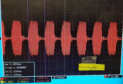
Pulse Output of the PGM-2 with different modulating wave shapes at 1,000,000 hz
The Output is Always a Pulse
Spectrum Showing Sidebands of Different Modulating Wave Shapes of 1,000,000 hz


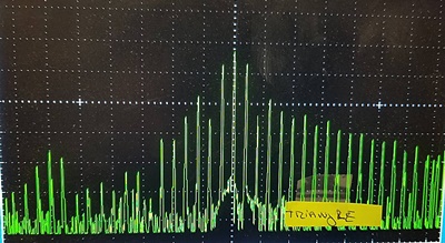
The PGM-2 has a carrier wave of 27,120,000 hz
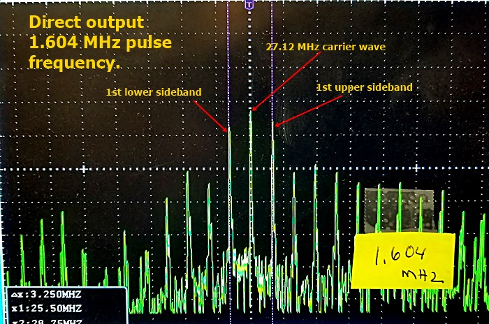
The photo below demonstrates how the direct frequency output method appears on a spectrum analyzer. The carrier wave of the PGM-2 is 27.12 Mhz, and that is shown at the center of the screen. The sidebands can be seen to each side of the carrier wave. On the lower left of the photo is a box showing the measurements X1 and X2. X-1 and X2 are the frequencies of the sidebands. X1 and X2 may not read out exactly due to limitations of the equipment.
Direct output of 1,604,000 hz at 60% duty cycle square wave
Upper sideband =27,120,000hz + 1,604,000 hz = 28,724,000 hz
Lower Sideband = 27,120,000 hz - 1,604,000 hz = 25,516,000 hz
Below are some photos showing the first method the PGM-2 can utilize to create frequencies much higher than it's modulation limits of 5.5 MHz. This is done via the use of harmonics of the modulating signal frequency to create sidebands. Both upper and lower sidebands are utilized in this method.
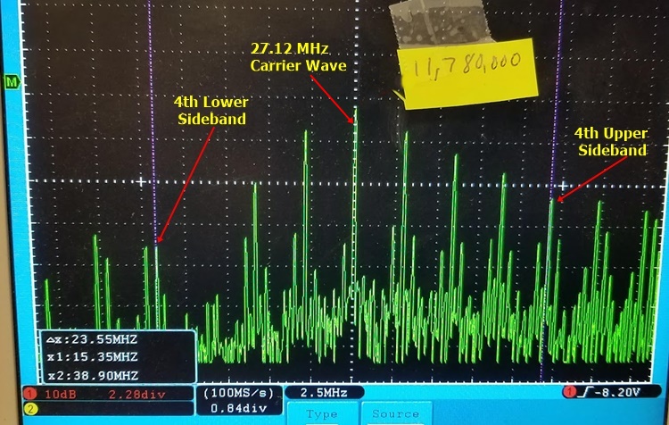
Harmonic Sideband Matching to 11,780,000 hz using the 4th harmonic of 2,945,000 hz ( 4 x 2945000 = 11,780,000)
Upper Sideband = 27,120,000 hz + 11,780,000 hz = 38,900,000 hz
Lower Sideband = 27,120,000 hz - 11,780,000hz = 15,340,000

Harmonic Sideband Matching to 17,033,662 hz using the 6th harmonic of 2,838.943.66 hz ( 6 x 2838943.66 = 17,033,662 )
Upper Sideband = 27,120,000 hz + 17,033,662 hz = 44,153,662 hz
Lower Sideband = 27,120,000 hz - 17,033,662 hz = 10,086,338
The photos below shows a second method the PGM-2 can utilize to create frequencies outside of it's modulation limits. This is the harmonic frequency matching method . In this method, only one of the sidebands will manifest at the desired frequency and be utilized . For the photo examples below, all harmonic matched frequencies are lower than 27.12 MHz. Being so, only the lower sidebands are utilized. With this method, harmonic matched frequencies that are higher than 27.12 Mhz, would use only the upper sidebands.
Comment: My spectrum analyzer does not measure precisely but is very close - example 11.78 Mhz below reads as 11.80 Mhz ( cursor X1)
In all the photos cursor X2, is set at the carrier frequency of 27.12 Mhz ( reads as 27.10 Mhz ) . What one obtains through this method is an exact frequency that is pulsed millions of times a second , and each pulse in the examples shown are less than 200 nanoseconds in duration. If one subtracts X1 from X2, ( i.e. 27.12 Mhz - 11.78 Mhz = 15.340 Mhz ) one obtains the difference between them. This is then used to calculate out the modulation frequency which will produce the desired harmonic matched frequency. In the photo below, the modulation frequency is 3,068,00hz ( 15,340,000 / 5 = 3.068 Mhz), and a 11,780,000 hz signal is then created as the 5th harmonic.
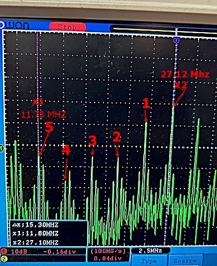
Above - 11.78 MHz signal , as 5th harmonic of 3,068,000 hz
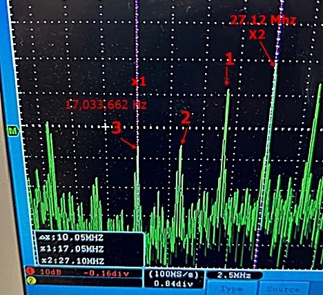
Above - 17,033,662hz signal, as 3rd harmonic of 3,362,112.666hz
27.12Mhz - 17,033,662 hz = 10,086,338hz
10,086,338/ 3 = 3,362,112.666 hz
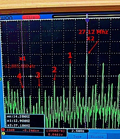
Above - 12.883 MHz signal, as 4th harmonic of 3,571,450 hz
27.12 MHz - 12.833 Mhz = 14,287,000hz
14,287,000/4 = 3,571,450 hz
Phone 505-239-1886